Where Is the Energy in an Electrical Circuit? Myth and Reality
1. Introduction
Modern education imposes a persistent way of thinking in which energy supplied by a power source is converted into heat, light, motion, and other forms of energy. It is also commonly believed that there is no energy in space. Your picture of the world is distorted by education, so you will not try to look for energy where there is none.
The drift velocity of free electrons in a metal conductor is only about 26 centimeters per hour — a speed so slow that grass grows faster. If electrical energy were transported by the electrons themselves, it would take years for the power generated at a power station to reach the lamp in your room.
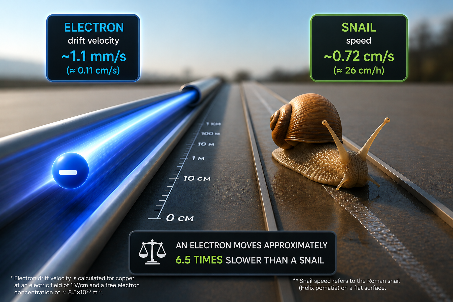
Fig. 1. Electron drift velocity in a conductor. (Click to enlarge to 4K)
To resolve this fundamental contradiction, an artificial model was created in which a metal conductor is assumed to be so densely filled with free electrons that pushing one electron transfers the impulse through the entire chain of subsequent electrons — similar to a tube filled with balls. However, a fundamental question remains: how do electrons "know" which direction they should move — from one terminal of the power source to the other, rather than in the opposite direction? What creates the initial impulse and determines the direction of the subsequent motion of charges? The electron-based model itself does not provide an answer to this question.
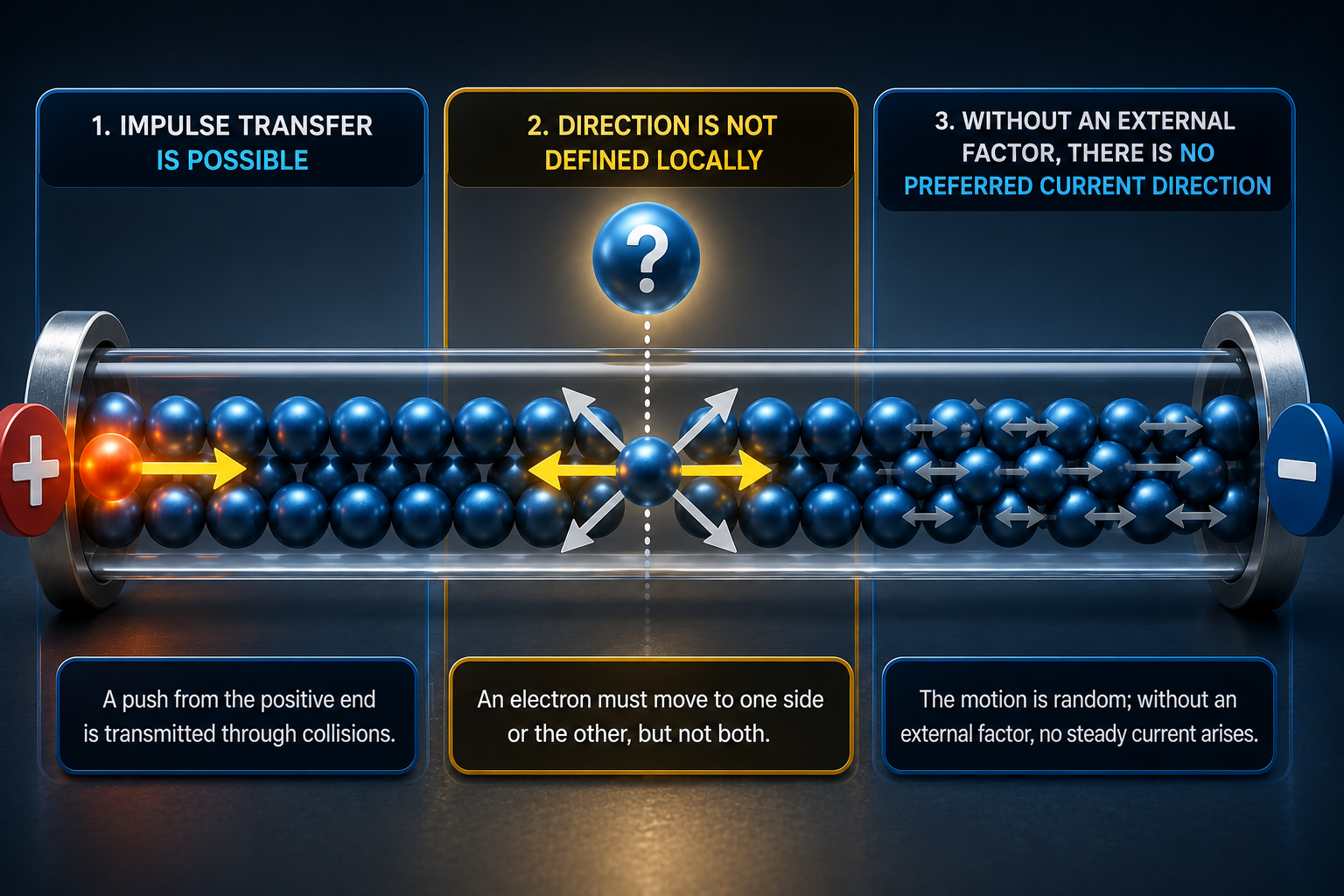
Fig. 2. Electron direction in a conductor. (Click to enlarge to 4K)
The answer to what initiates the motion of electric charges and determines its direction is found in the electrodynamics of James Clerk Maxwell, the British physicist whose equations laid the foundation for classical electrodynamics by describing the relationship between electric and magnetic fields.
When an electrical circuit is closed, an electric field is created instantly. An electric field does not require the existence of free charge carriers and exists in regions of space where such carriers are absent.
As it propagates along the conductor, the electric field causes a redistribution of free charges, resulting in the formation of surface charges at the conductor–dielectric boundary.
The movement of surface charges creates a magnetic field. The directions of electric and magnetic fields are described in detail in electrodynamics textbooks, but the traditional explanation of electrical circuit operation does not consider the fact that the energy flux density and its direction are described by the Poynting vector S = E × H.
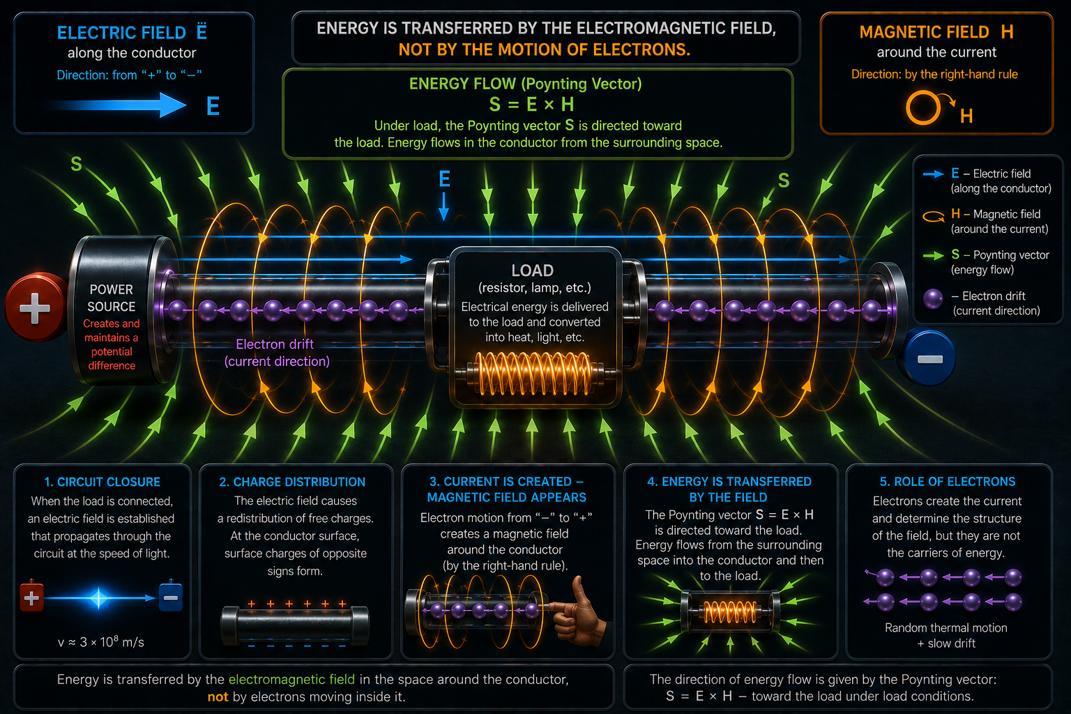
Fig. 3. The Poynting vector shows energy flow into the conductor. (Click to enlarge to 4K)
In 1884, Oliver Heaviside, while developing the concept of electromagnetic energy flow described by the Poynting vector S = E × H, showed that in an electrical circuit the Poynting vector is directed from the surrounding electromagnetic field into the conductor. The electric current in the conductor forms electric and magnetic fields, creating the conditions for energy to enter the conductor from the surrounding space.
▸ Key conclusion: energy exists in the surrounding space in the form of an electromagnetic field and does not belong to the power source.
Unlike the erroneous concepts formed by traditional education, classical electrodynamics shows that energy enters the load from the surrounding space, where it gives rise to other forms of energy: heat, light, and mechanical motion.
Maxwell's electrodynamics not only shows where the energy resides, but also identifies the mechanism by which this energy is utilized in an electrical circuit. This mechanism is the self-induced electromotive force (self-induced EMF).
According to classical theory, self-induced electromotive force (self-induced EMF) arises when the electric current changes and is described by the relation:
This relation implies that the magnitude of the self-induced EMF is determined by the rate of change of the current dI/dt. It forms the basis for the analysis of self-induction in electrical circuits.
2. James Maxwell's Insight
Classical electrical circuits are based on closed circuits with conduction currents. Maxwell's electrodynamics describes a more general process — the transfer of energy through electromagnetic fields, which does not require conduction currents, as demonstrated by radio communication.
The following schematic demonstrates how energy associated with the electromagnetic field can be obtained and utilized by using self-induced EMF to charge a capacitor without creating a closed circuit for conduction current.
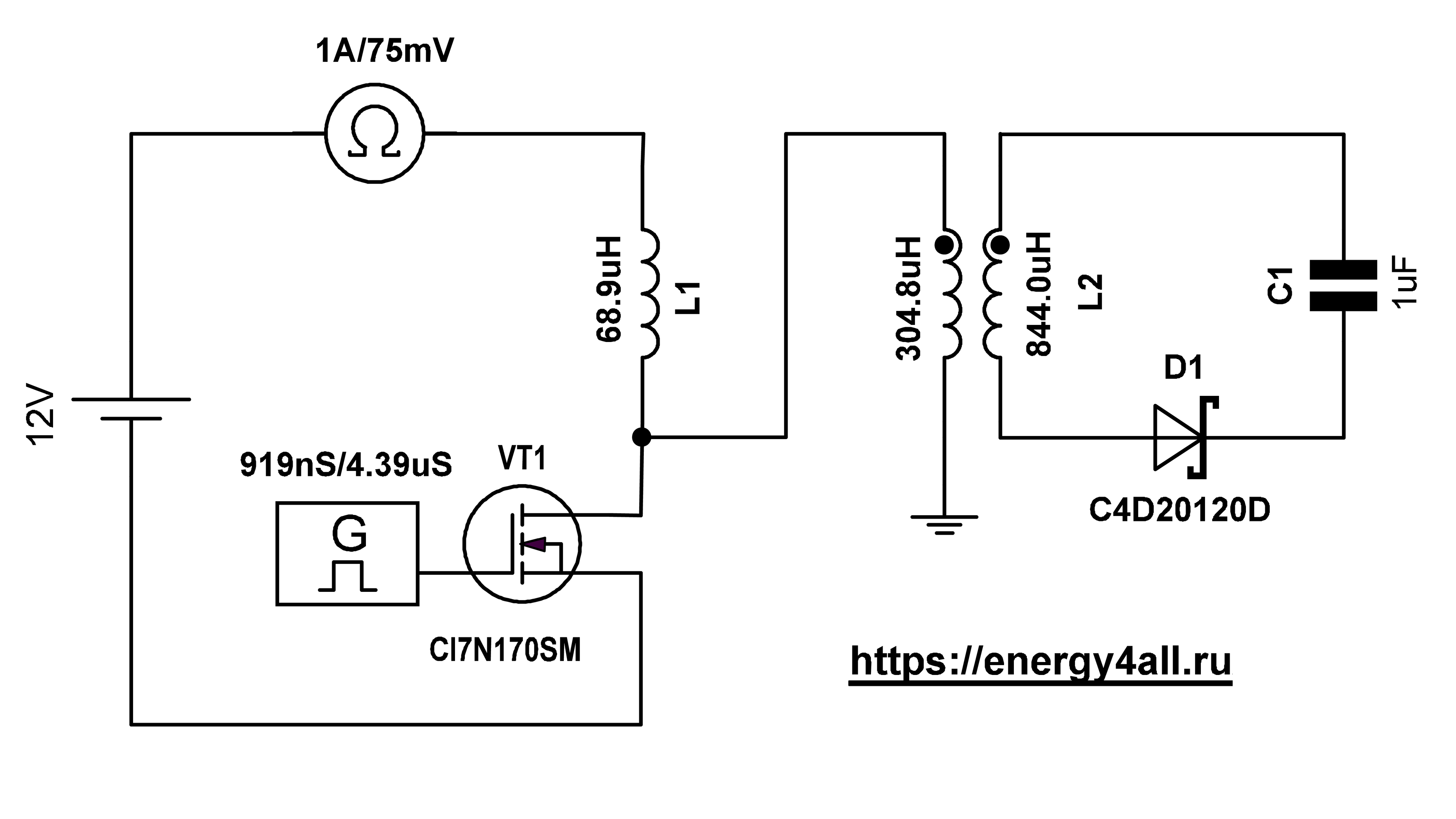
Fig. 4. Experimental setup schematic. (Click to enlarge to 4K)
3. Experimental Setup
3.1. Circuit Configuration
-
Power Supply: The ODP6033 is a linear power supply with a 50 Hz transformer. Current measurement accuracy: ≤ 0.1% + 8 mA.
To verify the repeatability of the observed effect, measurements were also performed using independent power sources: an automotive jump starter, a gasoline generator, and a TERMO 1012 UPS (1000 W, 12 V). The observed behavior remained consistent in all cases. - Switching Device: A CI7N170SM transistor with controlled on-time duration was used as a switching element. The transistor is connected in series with coil L1 and interrupts the connection between L1 (68.9 μH) and the negative terminal of the power supply.
- Grounding: The grounding system was implemented according to GOST requirements using a dedicated conductor. It was not connected to the protective earth of the mains supply and was used only within the experimental setup.
-
Oscilloscope: A Siglent SDS1204X-E oscilloscope was used (200 MHz bandwidth, 1 GSa/s sampling rate). The instrument allows reliable recording of pulse edges with durations of approximately 2–3 ns and longer.
The pulse edges observed in the experiments were in the tens-of-nanoseconds range and were therefore recorded without significant distortion caused by oscilloscope bandwidth limitations. - Coil L1: The inductance of coil L1 is 68.9 μH. One terminal is connected to the positive terminal of the power supply, and the other terminal is connected to the drain of the switching transistor.
-
Air-core Transformer L2:
The primary winding L2.1 (304.8 μH) is connected at one end to the transistor drain. The second terminal of L2.1 can operate in two configurations:
- floating terminal ("without ground" mode);
- connected to actual earth ground ("with ground" mode).
The secondary winding L2.2 (844 μH) charges a 1 μF storage capacitor through a C4D20120D Schottky diode. The diode anode is connected to the L2.2 terminal located on the grounding side.
Coil L1 and transformer L2 are physically separated and have no magnetic coupling. The only connection between them is the electrical connection through the transistor drain.
In this context, galvanic isolation refers only to the absence of a closed path for conduction current. It does not exclude electromagnetic coupling between elements through electric and magnetic fields, displacement currents, and field energy transfer.
4. Experimental Results
4.1. Effect of Grounding on Capacitor Charging
The video below demonstrates the operation of the circuit and the tuning procedure. It shows not only the restoration of the power supply energy balance (where the net energy exchanged with the power supply approaches zero), but also an increase in the capacitor charge when the circuit is connected to earth ground.
4.2. Measurement Results
Without Grounding: With the ground connection disconnected, the 1 μF capacitor charges to approximately 12 V. The current drawn from the power supply is zero. Energy stored in the capacitor in this mode:
With Grounding: After connecting the circuit to earth ground, the current drawn from the power supply increases to 0.017 A. This indicates that the energy balance between the energy delivered by the power supply and the energy returned to it is no longer zero. At the same time, the capacitor charges to 100 V. Energy stored in the capacitor:
The next part of the video demonstrates that, by adjusting the pulse repetition frequency, the energy balance between the energy delivered to the circuit and the energy returned to the power supply can be restored to zero. This condition is verified by the ammeter of the power supply.
The operating point with a non-zero energy balance was intentionally selected to demonstrate the tuning process and the effect of pulse repetition frequency.
After the energy balance has been restored, the power supply voltage is increased to 42 V. This change does not affect the energy balance. The capacitor charges to 306 V while the current drawn from the power supply remains zero. Energy stored in the capacitor under these conditions:
Comparison with the "without grounding" mode: 46800 / 72 ≈ 650
4.3. What Does a Zero Ammeter Reading Indicate?
What Does a Zero Ammeter Reading Indicate? A zero reading on the ammeter of the OWON ODP6033 laboratory power supply (as well as other digital power supplies) does not necessarily indicate the absence of current. Instead, it indicates a balance between the energy delivered by the power supply to the circuit and the energy returned from the circuit back to the power supply.
The built-in ammeter in such experiments should not be interpreted as a direct measurement of the power consumed by the circuit from the power supply. A zero reading indicates only that the energy delivered and the energy returned are equal over the instrument's averaging interval; it does not imply that current is absent.
5. Physical Mechanism of the Process
The physical principles underlying the proposed circuit have been known for more than a century:
- 1861 — James Clerk Maxwell introduced the concept of displacement current.
- 1865 — Maxwell published A Dynamical Theory of the Electromagnetic Field.
- 1873 — Maxwell published A Treatise on Electricity and Magnetism.
- 1884 — John Henry Poynting introduced the Poynting vector, describing the density and direction of electromagnetic energy flow.
During transistor turn-off, a time-varying electric field is established at the circuit interruption point (the transistor drain). When earth ground is connected, this electric field extends along the conductor between the transistor drain and the grounding point. The electric field within the conductor gives rise to a distribution of surface charges, which establishes the boundary conditions for the surrounding electric field E. The surface-charge distribution is governed by Maxwell's equations together with the continuity equation, ∂ρ/∂t + div J = 0, which expresses the local conservation of electric charge.
A time-varying electric field produces a displacement current which, according to the Maxwell–Ampère equation, curl H = J + ∂D/∂t, determines the curl of the magnetic field. Consequently, the displacement current generates a circulating magnetic field H in the surrounding space, whose field lines are tangent to the surface of the conductor.
The Poynting vector, S = E × H, is determined by the electric and magnetic fields E and H. In the presence of a load, it is directed from the surrounding space into the conductor. This indicates that electromagnetic energy enters the load from the surrounding field rather than being transported through the conductor. The energy delivered to the capacitor should not be regarded as originating from the earth connection.
In the galvanically isolated L2.1 circuit, there is no conduction current because there is no closed path for charge flow. Energy in L2.2 is induced as a result of electromagnetic energy transfer through the surrounding field to L2.1.
In the closed L2.2–diode–capacitor circuit, a conduction current is established. This current is rectified by the diode and accumulated in the capacitor.
According to the Faraday–Maxwell law of electromagnetic induction, dI/dt (the rapid change of current in coil L1 caused by the transistor turn-off) acts as an additional energy-transfer mechanism: it generates a self-induced EMF, which produces a high-voltage pulse.
A voltage pulse cannot exist without a conduction current. In this case, the reverse current (13.3 A) returns to the power supply through a closed circuit formed by the freewheeling diode and the transistor junction capacitance or through displacement currents.
The power supply creates the conditions required for the formation of the field structure between the transistor drain and earth ground. At the same time, the rate of current change in coil L1, dI/dt, generates a return current that is adjusted to achieve a balance between the energy drawn from the power supply and the energy returned to it. This balance is identified either by a zero current reading on the power supply or by an increase in battery charge.
6. References and Background Materials
- Igal Galili, Elisabetta Goihbarg. Energy transfer in electrical circuits: A qualitative account.
- Richard P. Feynman. The Feynman Lectures on Physics, Vol. II, Chapter 27. Field Energy and Field Momentum.
- Matar M., Welti R. Surface charges and J. H. Poynting's disquisitions on energy transfer in electrical circuits.
- Basil S. Davis, L. Kaplan. Poynting Vector Flow in a Circular Circuit.
- Poynting vector. Electromagnetic energy flux.
- Oliver Heaviside. Contributions to electromagnetic theory and energy flow.
- James Clerk Maxwell. Electromagnetic theory.
- Maxwell's equations and electromagnetic field theory.
