Capacitance-Independent Resonant Charging of Capacitor with Zero Supply Current
Abstract
The paper presents the results of an experimental investigation of a resonance whose frequency is determined by distributed capacitance rather than by a discrete capacitor connected to the circuit. The experimental results show that varying the capacitor value from 0.47 μF to 4.7 μF does not change the resonance frequency, while the average current drawn from the power supply remains zero. A video demonstrating the procedure for tuning the system to the operating point is also provided.
1. Introduction
In classical circuit theory, the resonance frequency of an electrical circuit is described by Thomson's resonance formula, in which the oscillation frequency is determined by the circuit inductance and capacitance. For an LC resonant circuit, the resonance frequency is uniquely determined by the capacitance of the capacitor connected to the circuit.
This paper presents the results of an experimental investigation of a resonant regime in which this relationship is no longer observed. The experimental results show that the resonance frequency is independent of the value of the discrete capacitor connected to the circuit and is instead determined by distributed capacitance. Varying the capacitor value from 0.47 μF to 4.7 μF produced no measurable change in the resonance frequency.
A key experimental observation is that, in the steady-state resonant regime, short-circuiting the capacitor terminals does not affect the average current drawn from the power supply. This observation indicates that the capacitor does not participate in the resonant energy exchange and that the resonance is sustained by energy stored in the distributed capacitance.
It is important to note that, in this circuit, the capacitor is charged through a Schottky diode. However, although a voltage is present across the capacitor, it does not determine the resonance frequency and does not affect the average current drawn from the power supply. These observations suggest that energy is delivered to the capacitor through the electromagnetic field, while the capacitor itself does not form part of the resonant system that determines the operating frequency.
Furthermore, in the steady-state resonant regime, the average current drawn from the power supply is zero, indicating a balance between the energy supplied to the circuit and the energy returned to the source due to the self-induced EMF.
2. Experimental Setup
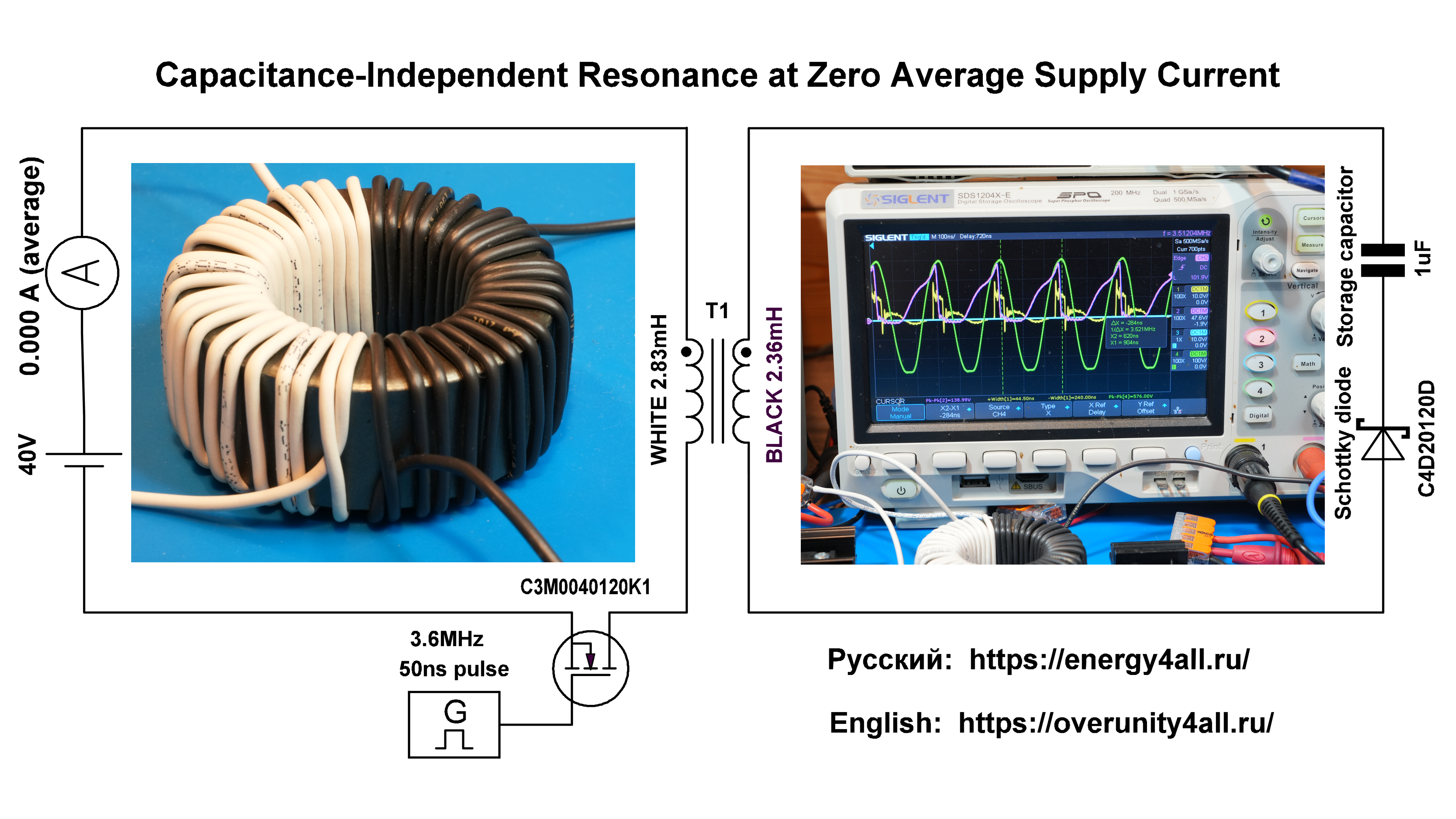
Fig. 1. Experimental circuit schematic. (Click to enlarge to 4K)
2.1. Circuit Topology
Primary circuit: OWON ODP6033 laboratory power supply (12–50 V) is connected to the primary winding of T1, which is connected to the drain of Q1. The source of Q1 is connected to the negative terminal of the power supply. Q1 operates as a low-side switch in a common-source configuration.
Secondary circuit: A series connection of diode D1 and capacitor C1 is connected in parallel with the secondary winding Ls.
Gate drive: The DGE2070 generator, operating in manual mode, defines the switching frequency and pulse duration. The control signal is transmitted through the ISO721MD optocoupler to the 1EDN6550B gate driver, which controls transistor Q1.
Measurements: The yellow oscilloscope trace corresponds to the gate voltage of Q1, the burgundy trace corresponds to the drain voltage of Q1 (white wire, primary winding of T1), and the green trace corresponds to the voltage on the secondary winding (black wire).
Power supply: All measurements were performed with the system powered by an autonomous Termo 1012 supply connected to a car battery. This eliminates interference from the mains network and ensures a clean experimental environment.
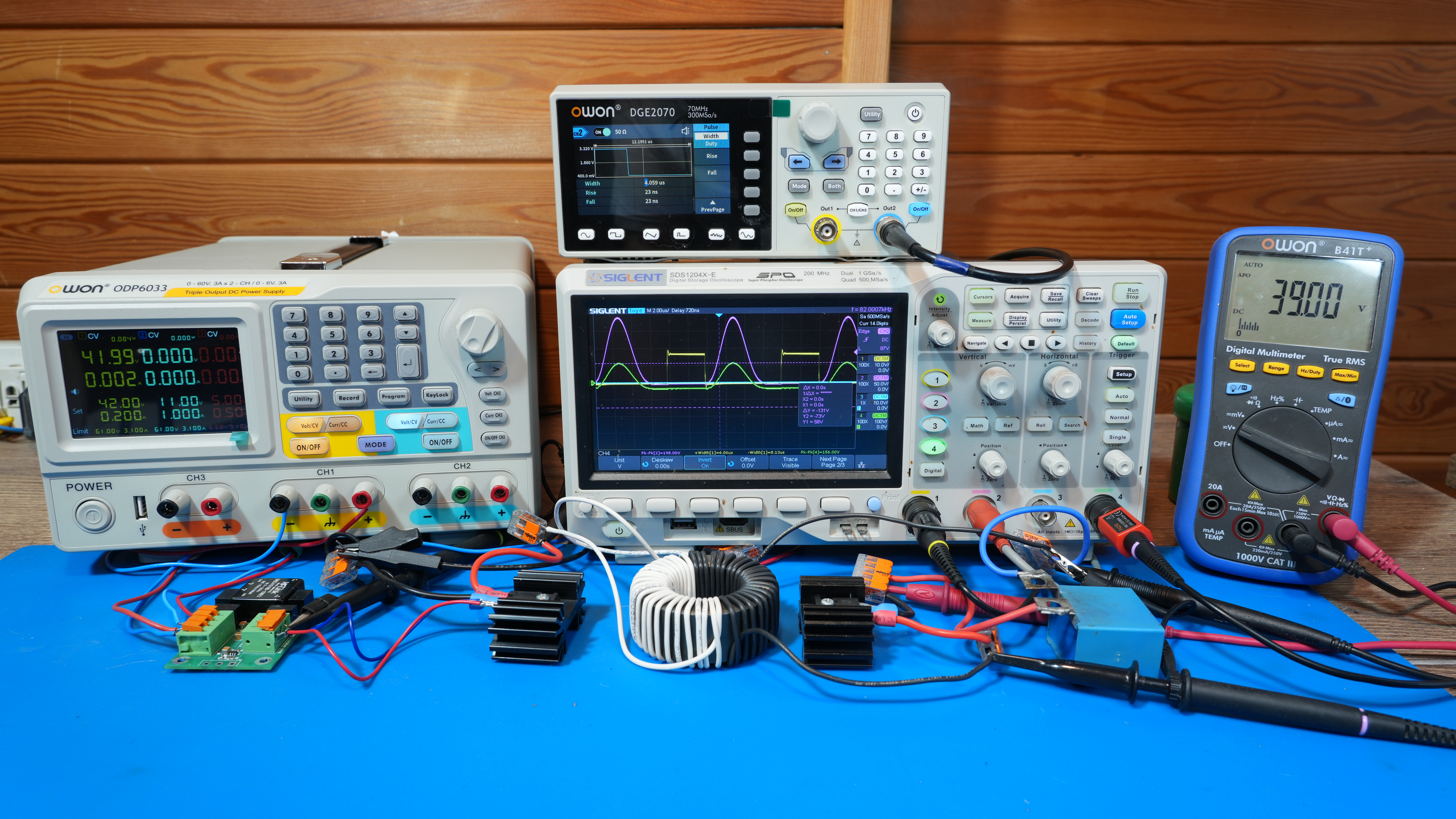
Experimental setup: DGE2070 signal generator, ferrite ring transformer, C3M0040120k1 SiC MOSFET configured as a low-side switch, C4D20120D SiC Schottky diode, 1EDN6550B gate driver with optocoupler isolation, OWON ODP6033 laboratory power supply, and digital voltmeter for monitoring the storage capacitor voltage. (Click to enlarge to 4K)
3. Measurement Methodology
- Power supply: OWON ODP6033 programmable DC power supply (used for powering the experimental setup and monitoring the supply current).
- Signal Generator: DGE2070 (manual adjustment of switching frequency and pulse duration for MOSFET control).
- LCR Meter: MS5308 (measurement of inductance and capacitance at 100 kHz).
- Oscilloscope: Siglent SDS1204X-E (200 MHz bandwidth, 1 GSa/s sampling rate).
- Multimeter: B41T (measurement of the voltage across the storage capacitor C1).
- Oscilloscope probe connections: All oscilloscope ground leads were connected to the negative terminal of the power supply (common reference point).
- Oscilloscope channels: Yellow trace — Vgs (gate-source voltage), burgundy trace — Vds (drain-source voltage), green trace — voltage on the secondary winding of T1.
4. Experimental Results
4.1. Video Demonstration of Capacitance-Independent Resonance Tuning
The video begins with a demonstration of the waveforms at a generator frequency of 80 kHz. The oscilloscope shows a high-voltage self-induced EMF pulse on the primary winding (burgundy trace) and a signal on the secondary winding (green trace) with an identical waveform signature.
The short-circuit condition is then demonstrated. In this mode, the current in the primary winding increases several-fold, causing the protection circuit of the power supply to activate.
Note: The self-induced EMF pulse occurs after the MOSFET has been fully turned off. The time shift between the EMF pulse and the yellow oscilloscope trace (Vgs) indicates this delay.
When the pulse duration is varied by more than a factor of two, the amplitude of the self-induced EMF pulse remains unchanged.
It is important to emphasize: that the observed phenomenon does not contradict physics; rather, it challenges the established engineering interpretation that associates energy transfer from the primary to the secondary winding of a transformer exclusively with conduction current in the circuit. According to Maxwell's equations, energy in electromagnetic systems is transferred through electromagnetic fields. The source of the induced EMF is the time variation of magnetic flux (∂B/∂t), determined by the electromagnetic field distribution, rather than by the conduction current itself.
Next, the video shows the pulse duration being reduced to 50 ns, followed by a gradual increase in the generator frequency to three or more megahertz. At a certain point, a loss of correspondence occurs, and the waveform on the secondary winding no longer matches the waveform on the primary winding.
Pronounced resonant oscillations appear on the secondary winding (green trace). The frequency of the signal generator is then adjusted to match the frequency of these oscillations.
It should be noted that after the appearance of harmonic oscillations on the secondary winding, short-circuiting the secondary winding no longer affects the current consumption from the power supply. The voltage across the capacitor, measured by the voltmeter, begins to increase and reaches hundreds of volts, compared with the initial value of 38 V.
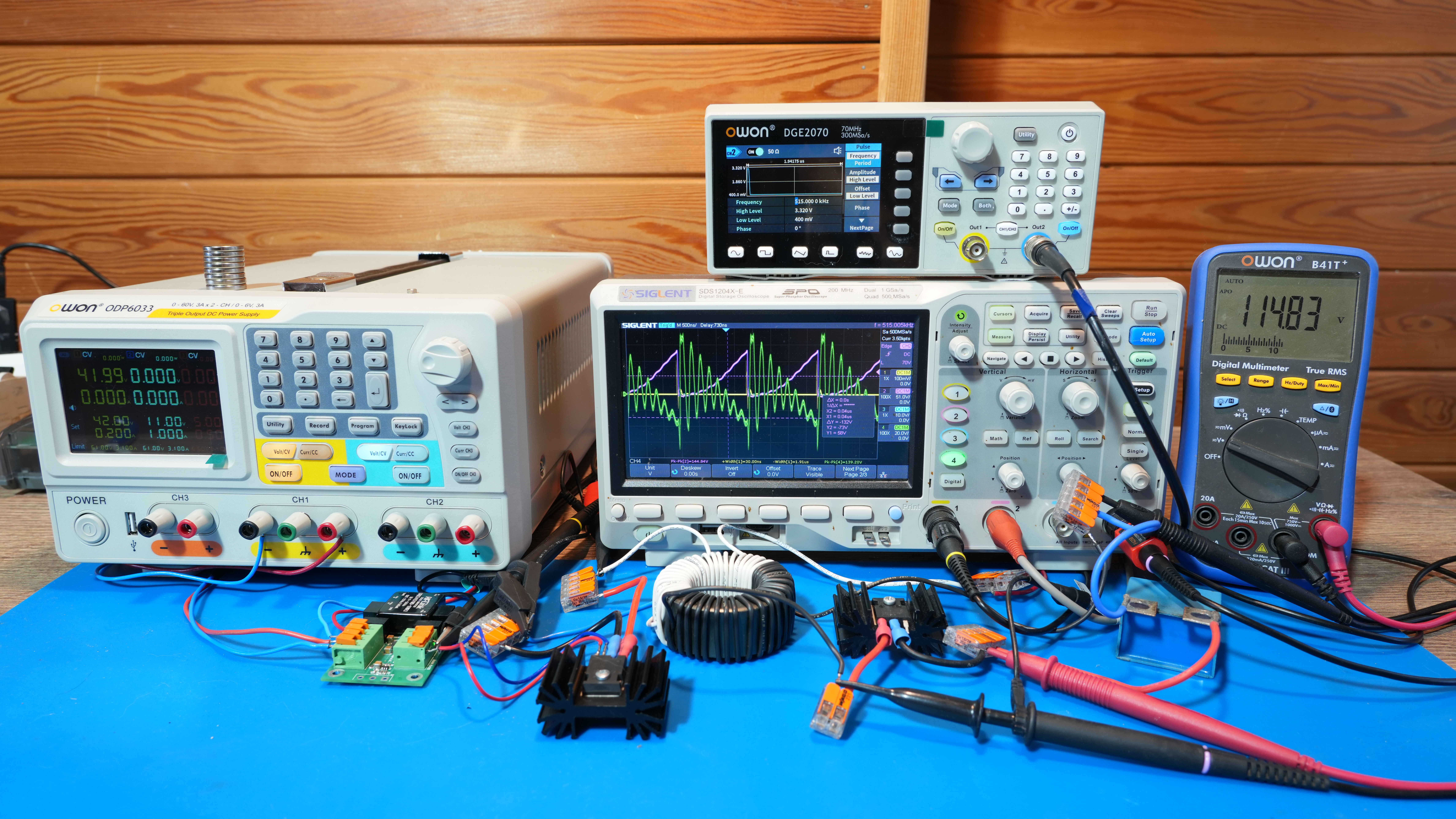
Oscillogram: harmonic sinusoidal oscillations on the secondary winding (green trace, 100 V/div), with an amplitude of 139 V. (Click to enlarge to 4K)
In the third part of the video, after setting the generator to the resonant frequency identified during the initial tuning stage, the green trace shows harmonic sinusoidal oscillations reaching 500 V.
The amplitude of the harmonic oscillations is four times higher than the self-induced EMF pulse on the primary winding, despite the equal number of turns and approximately equal inductance of the primary and secondary windings of the ferrite-ring transformer.
While harmonic oscillations are observed on the secondary winding, the waveform on the primary winding has a sawtooth shape.
It is also worth noting that the amplitude of the harmonic oscillations on the secondary winding reaches 500 V, compared with 160 V on the primary winding. Given the equal number of turns and approximately equal inductance of the windings, this contradicts the conventional understanding of the transformer turns ratio.
All of this occurs on a single closed magnetic core, which is inconsistent with the classical interpretation of transformer operation.
At the end of the video, the voltage across the storage capacitor is shown to have increased to 300 V. Short-circuiting the capacitor plates, and therefore the secondary winding, does not affect the average current consumption, which remains equal to zero. Connecting an additional 1 µF capacitor in parallel with the storage capacitor does not affect either the resonant frequency or the zero average current.
5. Discussion
5.1. Key Mechanism: Interruption of the Self-Induced EMF Variation
The classical approach considers energy transfer through conduction current. However, a different mechanism is observed in this experiment.
A sawtooth waveform is observed on the primary winding. The sharp drop of the sawtooth waveform coincides with the maximum amplitude of the harmonic oscillations on the secondary winding.
The abrupt interruption of the self-induced EMF pulse — reaching hundreds of volts — initiates a rapid change in magnetic flux density (∂B/∂t), creating the conditions for charge accumulation on the capacitor in the secondary circuit from the electromagnetic field of the surrounding environment.
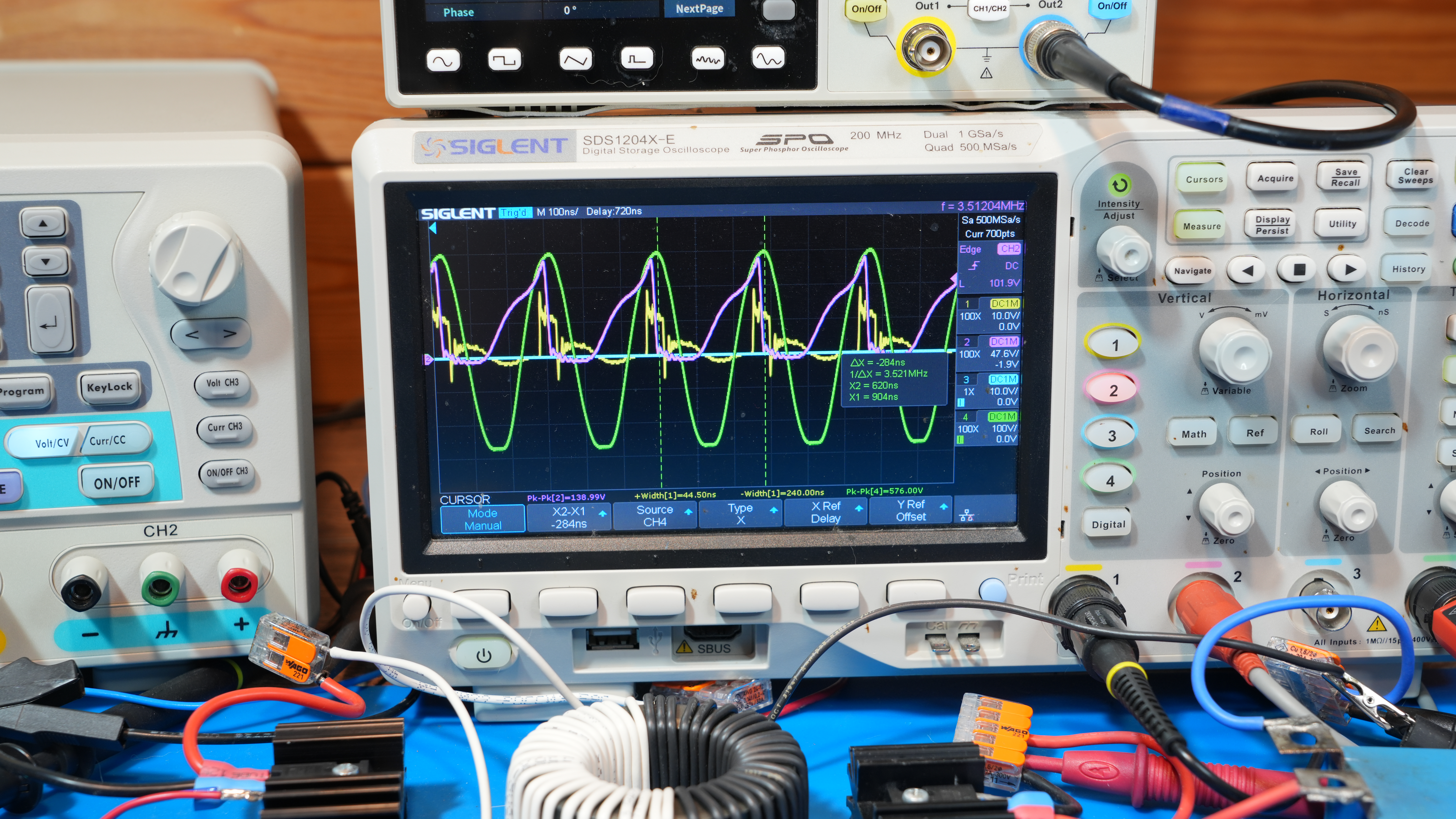
Oscillogram: yellow — Vgs (gate, 10 V/div.), burgundy — Vds (drain, 50 V/div.), green — secondary winding voltage (100 V/div.). (Click to enlarge to 4K)
5.2. Contradictions to Classical Circuit Theory
Classical circuit theory, based on integral parameters, does not describe this mechanism:
-
Transformation ratio
For an equal number of turns (N₁ = N₂), classical transformer theory predicts equal voltages on the primary and secondary windings. In the experiment, the voltage on the secondary winding reaches 500 V, while the primary winding shows 160 V. The resulting voltage ratio of 3.1 cannot be explained by the linear transformer model. -
Energy transfer through current
In classical theory, energy transfer is associated with conduction current. However, during the current conduction interval, no corresponding signal is observed on the secondary winding. Energy transfer occurs after the switch is turned off, when the self-induced EMF pulse appears. -
Short-circuiting the secondary winding
In a classical transformer, short-circuiting the secondary winding causes an increase in the primary current and leads to higher power consumption. In the experiment, short-circuiting the secondary winding does not affect the average current drawn from the power supply, which remains zero. -
Resonant frequency
The classical Thomson formula predicts that the resonance frequency depends on capacitance:f = 1 / (2π√(LC))In the experiment, adding a parallel capacitor does not change the resonance frequency. -
Two different signal patterns on a single closed magnetic core
Under the same conditions and on the same closed magnetic core, a sawtooth waveform is observed on the primary winding, while the secondary winding exhibits harmonic sinusoidal oscillations. Classical transformer theory assumes that the magnetic flux in a closed core is common to all windings; therefore, the induced voltages should have the same waveform. The observed difference indicates that the energy accumulated on the storage capacitor is not determined solely by the common magnetic flux. -
Energy source identification
The measured average current drawn from the power supply is zero, while the voltage on the storage capacitor increases. This indicates that the energy accumulated in the secondary circuit cannot be explained by conventional power transfer from the primary circuit. -
The operating frequency exceeds the classical limits of the ferromagnetic material
The resonant frequency at which harmonic oscillations with an amplitude of 500 V are observed reaches several megahertz. For the 63×38×25 mm MnZn ferrite ring, typical parameters are: relative magnetic permeability μr ≈ 2000–3000 (at low frequencies) and a recommended operating frequency range below approximately 1–2 MHz. Classical theory predicts that above this range, the permeability decreases significantly and magnetic losses increase. The observation of stable resonance above 3 MHz cannot be explained by the classical frequency limitations of ferromagnetic materials.
5.3. Explanation Through Maxwell's Equations
All observed effects are described within the framework of Maxwell's equations:
5.3.1 Faraday–Maxwell Law
- The sawtooth waveform on the primary winding indicates a non-uniform change in magnetic flux.
- The sawtooth decline coincides with the maximum amplitude of harmonic oscillations on the secondary winding.
- This means that at the moment of interrupting the EMF change, a maximum ∂B/∂t occurs, initiating the resonance process and the high voltage on the secondary winding.
5.3.2. Poynting Vector
Energy in electromagnetic systems is described by the electromagnetic field, not by the conduction current itself. Conductors guide the field distribution.
- Short-circuiting the secondary winding does not affect the measured average current consumption — the energy accumulation process is associated with the electromagnetic field.
- Adding a parallel capacitor does not change the observed resonance frequency — the resonance is determined by the distributed parameters of the electromagnetic system rather than by the added discrete capacitance.
5.3.3. Transformation Ratio in Field Representation
In a classical transformer, the voltage ratio is determined by the turns ratio:
For equal numbers of turns, the primary and secondary voltages should be equal. However, in the experiment, the secondary winding shows approximately 500 V, while the primary winding shows approximately 160 V. The voltage ratio of about 3.1 cannot be explained by the classical transformer model based only on the turns ratio.
Under resonance with distributed parameters, the field is redistributed. The EMF on each winding is determined not by the number of turns, but by the integral of E along the contour, which depends on the rate of flux change through the area enclosed by the contour.
5.4. Nature of Capacitance-Independent Resonance
The observed resonance does not depend on the added external capacitance. In a conventional LC circuit, the resonant frequency is determined by the inductance and capacitance:
Therefore, adding a parallel capacitor should significantly change the resonance frequency. However, in the experiment, the resonance frequency remains unchanged despite the addition of a large external capacitor.
This indicates that the observed resonance is determined not by a discrete capacitor, but by the distributed parameters of the electromagnetic system.
5.5. General Conclusion
Classical circuit theory operates with lumped parameters and does not fully account for:
- the role of the electromagnetic field in energy transfer;
- the distributed nature of electromagnetic parameters;
- the mechanism associated with interrupting the self-induced EMF pulse.
6. Conclusion
The experimental study has revealed and confirmed a stable mode of capacitance-independent resonance in a pulse transformer circuit with a closed ferrite magnetic core.
It is important to note that the effect was tested on ten different toroidal magnetic cores with different diameters, materials, and numbers of turns. In every case, the effect was reproduced consistently, exhibiting the same characteristic behavior but at different resonant frequencies. These frequency differences are explained by variations in winding inductance resulting from the number of turns, winding geometry, and core properties. This confirms both the physical nature of the observed phenomenon and its reproducibility under different experimental conditions.
It has been established that:
- Energy transfer from the primary to the secondary winding is associated not with the supply conduction current, but with the self-induced EMF pulse that occurs after the switching process is completed.
- The resonance frequency is determined by the distributed parameters of the electromagnetic system rather than by a discrete capacitor, as confirmed by the unchanged resonance frequency after changing the circuit capacitance and after adding a parallel capacitor.
- Short-circuiting the secondary winding does not affect the measured average supply current, which remains close to zero while the storage capacitor continues to accumulate charge.
- Harmonic sinusoidal oscillations with amplitudes of up to 500 V are observed on the secondary winding, whereas approximately 160 V is measured on the primary winding despite an equal number of turns. This voltage ratio cannot be explained by the classical transformer turns ratio.
- Two different signal waveforms exist simultaneously on the same closed magnetic core: a sawtooth waveform on the primary winding and harmonic sinusoidal oscillations on the secondary winding. This indicates that the energy accumulated on the storage capacitor is not formed solely by the common magnetic flux.
- The observed resonance frequency reaches several megahertz, exceeding the nominal operating frequency range of the ferrite material. This indicates that the observed process cannot be explained solely by the conventional magnetic core operating limits.
The observed phenomena do not contradict Maxwell's equations. It should be noted that classical engineering interpretations based on lumped parameters R, L, and C, as well as on the conventional transformer turns ratio, are insufficient to describe the observed behavior.
6.1. Practical Application and Prospects
The observed phenomenon opens new possibilities for the development of power conversion systems with potentially new operating characteristics:
- High Coefficient of Performance (COP) — in the experimentally observed mode, the measured average current drawn from the power supply approaches zero. Therefore, the conventional efficiency expression (η = Pout / Pin) becomes insufficient for describing this operating regime. The coefficient of performance (COP) can be used as an alternative parameter to characterize the relationship between the useful output and the measured energy input in this mode.
- EMF-Controller Control Device — a dedicated control device is currently being developed based on the Xilinx Zynq-7020 FPGA platform. It is designed for automatic tuning and stabilization of the capacitance-independent resonance mode. The device provides real-time monitoring of signal parameters, adjustment of operating frequency and pulse duration, and control of the storage capacitor discharge into a load, enabling controlled utilization of the accumulated energy. The working name of the device is "EMF-Controller" (Self-Induced EMF Controller).
6.2. Further Research Directions
- Mathematical modeling of the resonant mode based on Maxwell's field equations.
- Investigation of the influence of magnetic core properties and winding geometry on the resonance parameters.
- Development of engineering design and calculation methods for devices based on capacitance-independent resonance.
- Experimental investigation of the scalability of the observed phenomenon to higher power levels.
- Investigation of optimal materials and configurations for improved performance.
- Development and implementation of a control device based on the Xilinx Zynq-7020 FPGA platform for automatic tuning and stabilization of the resonant mode — "EMF-Controller".
